GEOMETRICAL OPTICS
4. PRISM
Z\section{PRISM}
(i) It is a transparent material the surface on which light is incident \& the surface from where light emerge should be plane but not parallel.
(ii) The angle between these two surfaces is known as angle of prism.
\(\mathrm{PQ}=\) Incident ray
\(\mathrm{QR}=\) Refracted ray
\(\mathrm{RS}=\) Emergent ray
\(\mathrm{A}=\) Prism angle
\(i_{1}=\) Incident angle on face \(\mathrm{AB}\)
\(i_{2}=\) Emergent angle on face \(\mathrm{AC}\)
\(\mathrm{r}_{1}=\) Refracted angle on face \(\mathrm{AB}\)
\(r_{2}=\) Incident angle on face \(A C\)

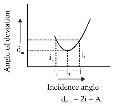
\section{Condition of Minimum Deviation :}
For minimum Deviation
Refracted ray QR should be parallel to base of the prism in this condition
\[
\mathrm{i}_{1}=\mathrm{i}_{2}=\mathrm{i}
\]
\(1 \times \sin i_{1}=\mu \sin r_{1}\)
\(\mu \sin r_{2}=1 \times \sin i_{2}\)
\(\because \quad \mathrm{i}_{1}=\mathrm{i}_{2}\)
\(m \sin r_{2}=\sin i_{1}\)
from (i) and (ii)
\[
\mathrm{r}_{1}=\mathrm{r}_{2}
\]
from \(\quad r_{1}+r_{2}=A \quad \Rightarrow \quad r+r=A \quad 2 r=A\)
\[
\mathrm{r}=\frac{\mathrm{A}}{2}
\]
Minimum devition \(\delta_{\min }=2 \mathrm{i}-\mathrm{A}\)
\[
\mathrm{i}=\frac{\mathrm{A}+\delta_{\min }}{2}, \mathrm{r}=\frac{\mathrm{A}}{2}
\]
if prism is placed in air \(\quad \mu_{1}=1\)
\(1 \times \sin \mathrm{i}=\mu \sin r\)
\(\sin \left(\frac{A+\delta_{\min }}{2}\right)=\mu \sin \frac{A}{2}\)
\(\mu=\frac{\sin \left[\frac{A+\delta_{\min }}{2}\right]}{\sin \frac{A}{2}}\)
If angle of prism is small \(\mathrm{A}<10^{\circ}, \sin \theta \approx \theta\)
\( \[
\begin{aligned}
& \mu=\frac{\frac{A+\delta_{\min }}{2}}{\frac{A}{2}} \quad \mu=\frac{A+\delta_{\min }}{A} \\
& \mathrm{~A}+\delta_{\min }=\mu \mathrm{A} \quad \delta_{\min }=(\mu-1) \mathrm{A} \text { for thin prism }
\end{aligned}
\] \)
\section{No Emergence Condition :}
Let maximum incident angle on the face \(\mathrm{AB} \mathrm{i}_{\max }=90^{\circ}\)
\( \[
1 \times \sin 90 \quad=\mu \sin r_{1}
\]\[
\sin r_{1}=\frac{1}{\mu}=\sin \theta_{C}
\] \)
\(\Rightarrow \quad \mathrm{r}_{1}=\theta_{\mathrm{C}}\)
if TIR occur at face \(\mathrm{AC}\) then
\(\begin{array}{ll} & \mathrm{r}_{2}>\theta_{\mathrm{C}} \\ \text { from } & \mathrm{r}_{1}+\mathrm{r}_{2}=\mathrm{A}\end{array}\) from (i) \& (ii)
from (iii) \& (iv)
\[
\begin{aligned}
& \mathrm{r}_{1}+\mathrm{r}_{2}>\theta_{\mathrm{C}}+\theta_{\mathrm{C}} \\
& \mathrm{r}_{1}+\mathrm{r}_{2}>2 \theta_{\mathrm{C}}
\end{aligned}
\]
\[
A>2 \theta_{C} \quad \frac{A}{2}>\theta_{C} \Rightarrow \sin \frac{A}{2}>\sin \theta_{C} \Rightarrow \sin \frac{A}{2}>\frac{1}{\mu} \Rightarrow \frac{1}{\sin \frac{A}{2}}<\mu
\]
Note :
(i) Angle of prism or refracting angle of prism means the angle between the faces on which light is incident and from which it emerges.
(ii) If the faces of a prism on which light is incident and from which it emerges are parallel then the angle of prism will be zero and as incident ray will emerge parallel to itself, deviation will also be zero, i.e., the prism will act as a transparent plate.
(iii) If \(\mu\) of the material of the prism is equal to that of surroundings, no refraction at its faces will take place and light will pss through it undeviated, i.e. \(\delta=0\).
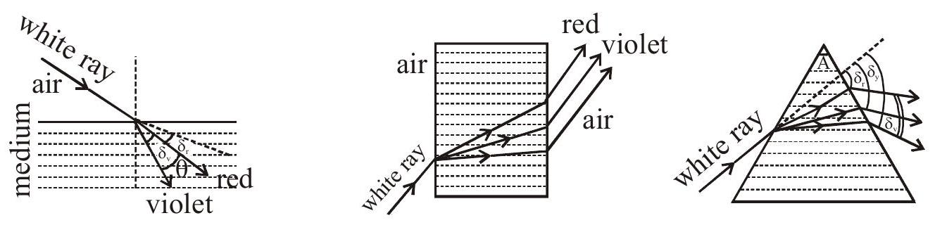
\section{DISPERSION OF LIGHT}
The angular splitting of a ray of white light into a number of components and spreading in different directions is called Dispersion of Light.
(a) Angle of Dispersion :
Angle between the rays of the extreme colours in the refracted (dispersed) light is called angle of dispersion. \(\theta=\delta_{\mathrm{v}}-\delta_{\mathrm{r}}\)
(b) Dispersive power \((\omega)\) of the medium of the material of prism is given by:
\[
\omega=\frac{\text { angular dispersion }}{\text { deviation of mean ray (yellow) }}=\frac{\theta}{\delta_{y}}
\]
For small angled prism \(\left(\mathrm{A} \leq 10^{\circ}\right)\) with light incident at small angle \(\mathrm{i}\)
\[
\omega=\frac{\delta_{v}-\delta_{r}}{\delta_{y}}=\frac{n_{v}-n_{r}}{n_{y}-1} \quad\left[\text { take } n_{y}=\frac{n_{v}+n_{r}}{2} \text { if value of } n_{y}\right. \text { is not given in the problem] }
\]
\(n_{v}, n_{r}\) and \(n_{y}\) are R. I. of material for violet, red and yellow colours respectively.
Note :
(i) \(\mathrm{n}-1=\) refractivity of the medium for the corresponding colour.
(ii) Cause of dispersion: Dependence of \(n\) on \(\lambda\). (from cauchy's Relation).
\section{COMBINATION OF TWO PRISMS :}
\section{Deviation without dispersion :}
For the combination of prism shown in figure, if there is to be no angular dispersion, then
\[
\left(\delta_{\mathrm{v}}-\delta_{\mathrm{r}}\right)+\left(\delta_{\mathrm{v}}^{\prime}-\delta_{\mathrm{r}}^{\prime}\right)=0
\]
or
or
\[
\left(\mu_{\mathrm{v}}-\mu_{\mathrm{r}}\right) A+\left(\mu_{\mathrm{v}}^{\prime}-\mu_{\mathrm{r}}^{\prime}\right) \mathrm{A}^{\prime}=0
\]
or \(\left(\mu_{v}^{\prime}-\mu_{r}^{\prime}\right) A^{\prime}=-\left(\mu_{v}-\mu_{r}\right) A\)
\[
A^{\prime}=-\left(\frac{\mu_{v}-\mu_{r}}{\mu_{v}^{\prime}-\mu_{r}^{\prime}}\right) A
\]
This is the condition for achromatism i.e., the condition for no dispersion. This condition can be written in another form as given below.
From equation (1),
\((\mu-1) \mathrm{A} \frac{\mu_{\mathrm{v}}-\mu_{\mathrm{r}}}{\mu-1}+\left(\mu^{\prime}-1\right) \mathrm{A} \frac{\mu_{\mathrm{v}}^{\prime}-\mu_{\mathrm{r}}^{\prime}}{\mu^{\prime}-1}=0\)
or
\[
\delta \omega+\delta^{\prime} \omega^{\prime}=0
\]
or
\[
\frac{\omega}{\omega^{\prime}}=-\frac{\delta^{\prime}}{\delta}
\]

Since, \(\omega^{\prime}>\omega, \quad \therefore \delta>\delta^{\prime}\)
or \(\quad(\mu-1) A>\left(\mu^{\prime}-1\right) A^{\prime}\)
But, \(\quad(\mu-1)<\left(\mu^{\prime}-1\right) \quad \therefore \mathrm{A}>\mathrm{A}^{\prime}\)
So, the crown glass prism should have a larger angle than the flint glass prism.
Net deviation \(=\delta+\delta^{\prime}\)
\[
\begin{aligned}
& =(\mu-1) \mathrm{A}+\left(\mu^{\prime}-1\right) \mathrm{A}^{\prime}=(\mu-1) \mathrm{A}\left[1+\frac{\left(\mu^{\prime}-1\right) \mathrm{A}^{\prime}}{(\mu-1) \mathrm{A}}\right] \\
& =(\mu-1) \mathrm{A}\left[1-\frac{\mu^{\prime}-1}{\mu-1} \frac{\mu_{\mathrm{v}}-\mu_{\mathrm{r}}}{\mu_{\mathrm{v}}^{\prime}-\mu_{\mathrm{r}}^{\prime}}\right] \quad \text { (Using equation (2)) } \\
& =(\mu-1) \mathrm{A}\left[1-\frac{\mu_{\mathrm{v}}-\mu_{\mathrm{r}}}{\mu-1} \times \frac{\mu_{\mathrm{v}}-\mu_{\mathrm{r}}}{\mu-1} \times \frac{\mu^{\prime}-1}{\mu_{\mathrm{v}}^{\prime}-\mu_{\mathrm{r}}^{\prime}}\right]=\delta\left(1-\frac{\omega}{\omega^{\prime}}\right)
\end{aligned}
\]
Since \(\omega^{\prime}>\omega\), therefore the net deviation is in the direction of the deviation produced by crown glass prism.
\section{Dispersion without Deviation :}
Let us consider a crown glass prism combined with a flint glass prism in position as shown in figure. Let A and \(A^{\prime}\) be the angles of crown glass prism and flint glass prism respectively. Let \(\mu_{0}, \mu\) and \(\mu_{\mathrm{r}}\) be the refractive indices of the crown glass for violet, yellow and red colours respectively.
Let \(\mu_{0}^{\prime}, \mu^{\prime}\) and \(\mu_{\mathrm{r}}^{\prime}\) be the corresponding values for the flint glass prism.
Let \(\delta\) and \(\delta^{\prime}\) be the deviations suffered by yellow light through crown glass prism and flint glass prism respectively.
If the combination does not produce any deviation, then
\[
\delta+\delta^{\prime}=0
\]
or \(\quad(\mu-1) \mathrm{A}+\left(\mu^{\prime}-1\right) \mathrm{A}^{\prime}=0\)
or \(\quad\left(\mu^{\prime}-1\right) \mathrm{A}^{\prime}=-(\mu-1) \mathrm{A}\)

or \(\quad \mathrm{A}^{\prime}=-\left(\frac{\mu-1}{\mu^{\prime}-1}\right) \mathrm{A}\)
This is the condition for no devition. The negative sign indicates that the two prisms are to be placed in position as shown in figure.
Net angular dispersion \(=\left[\left(\delta_{\mathrm{v}}-\delta_{\mathrm{r}}\right)+\left(\delta_{\mathrm{v}}^{\prime}-\delta_{\mathrm{r}}^{\prime}\right)\right]=\left(\mu_{\mathrm{v}}-\mu_{\mathrm{r}}\right) \mathrm{A}+\left(\mu_{\mathrm{v}}^{\prime}-\mu_{\mathrm{r}}^{\prime}\right) \mathrm{A}^{\prime}\)
\[
\begin{aligned}
& =\mathrm{A}\left[\left(\mu_{\mathrm{v}}-\mu_{\mathrm{r}}\right)+\left(\mu_{\mathrm{v}}^{\prime}-\mu_{\mathrm{r}}^{\prime}\right) \frac{\mathrm{A}^{\prime}}{\mathrm{A}}\right] \\
& =\mathrm{A}\left[\left(\mu_{\mathrm{v}}-\mu_{\mathrm{r}}\right)+\left(\frac{\mu-1}{\mu^{\prime}-1}\right)\left(\mu_{\mathrm{v}}^{\prime}-\mu_{\mathrm{r}}^{\prime}\right)\right] \\
& =(\mu-1) \mathrm{A}\left[\frac{\mu_{\mathrm{v}}-\mu_{\mathrm{r}}}{\mu-1}-\frac{\mu_{\mathrm{v}}^{\prime}-\mu_{\mathrm{r}}^{\prime}}{\mu^{\prime}-1}\right]=\delta\left(\omega-\omega^{\prime}\right)
\end{aligned}
\]
Here \(\omega\) and \(\omega^{\prime}\) are the dispersive powers of crown glass and flint glass respectively. As the dispersive powers \(\omega\) and \(\omega^{\prime}\) are not equal, in such a combination there will be resultant dispersion and the final dispersed beam is parallel to the incident beam.
Since \(\omega^{\prime}>\omega\) therefore the net angular dispersion is negative. This explains why the order of colours in the spectrum due to combination is opposite to that in the crown glass prism.
\section{Note :-}
(i)
\section{Spectra :}
Pattern produced by a beam emerging from a prism after refraction is called Spectrum. Types of spectrum:
(a) Line
Due to source in atomic state.
(b) Band : Due to source in molecular state.
(c) Continuous : \(\quad\) Due to white hot solid.
\section{In Emissive Spectrum:}
Bright colours or lines, emitted from source are observed.
\section{In Absorption Spectrum:}
Dark gap indicates frequencies absorbed.
(ii) Dispersive power like refractive index has no units and dimensions and depends on the material of the prism.
(iii) As for a given prism dispersive power is constant, i.e., dispersion of different wavelength will be different and will be maximum for violet and minimum for red (as diviation is maximum for violet and minimum for red)
\section{REFRACTION AT CURVED SURFACES}
\section{LAW OFREFRACTIONATSPHERICALSURFACE :}
When light passes from a medium of refractive index \(\mu_{1}\) to a medium of refractive index \(\mu_{2}\) by a spherical surface of radius of curvature \(R\) then the relation between object distance \(u\) and image distance \(v\) is given by
\[
\frac{\mu_{2}}{v}-\frac{\mu_{1}}{u}=\frac{\mu_{2}-\mu_{1}}{R}
\]
\section{Terms related to refraction at spherical surfaces :}
(A) Centre of curvature (C)
It is the centre of sphere of which the surface is a part.
(B) Radius of curvature (R)
It is the radius of the sphere of which the surface is a part.
(C) Pole (P)
It is the geometrical centre of the spherical refracting surface.
(D) Principal Axis
It is the straight line joining the centre of curvature to the pole.
(E) Focus (F)

When a narrow beam of rays of light, parallel to the principal axis and close to it (known as paraxial rays) is incident on a refracting spherical boundary, the refracted beam is found to converge or appear to diverge [depending upon the nature of the boundary (concave/canvex) and the refractive index of two media] from a point on the principal axis . This point is called focus.
\section{Cartesian sign convention}
(1) All distances are measured from the pole (P).
(2) Distances measured in the direction of incident rays are taken as positive.
(3) Distances above the principal axis are taken as positive.
(4) Angles measured from the normal in the anticlockwise sense are positive.

(i) It is not always necessary that for convex boundary the parallel rays always converge. Similarly for concave boundary the incident parallel ray may converge or diverge depending upon the refractive index of two media,
(ii) Laws of refraction are valid for spherical surface.
(iii) Pole, centre of curvature, Radius of curvature, Principal axis etc. are defined as spherical mirror except for the focus.

\section{LATERAL MAGNIFICATION :}
It is defined as
\[
\begin{aligned}
\mathrm{m} & =\frac{\mathrm{h}_{\mathrm{i}}}{\mathrm{h}_{\mathrm{o}}}=\frac{\text { height of image }}{\text { height of object }}=-\frac{\mathrm{v} / \mu_{2}}{-\mathrm{u} / \mu_{1}} \\
\mathrm{~m} & =\frac{\mu_{1}}{\mu_{2}} \cdot \frac{v}{\mathrm{u}}
\end{aligned}
\]
\section{LENS}
\section{Definition :}
A lens is a piece of transparent material with two refracting surfaces such that at least one is curved and refractive index of its material is different from that of the surroundings.
\section{Types of lenses :}

Depending upon the shape of the refracting surfaces following types of lenses can be formed:
\section{Terms related to thin spherical lenses :}
(A) Optical centre (O) is a point for a given lens through which any ray passes undeviated.
(B) Principal Axis \(\left(\mathbf{C}_{\mathbf{1}} \mathbf{C}_{2}\right)\) is a line passing through optical centre and perpendicular to the lens. The centre of curvature of curved surfaces always lies on the principal axis . (C) Principal Focus :
A lens has two surfaces causing two focul points
(i) First focal point is an object point on the principal axis whose image is formed at infinity.

(ii) Second focal point is an image point on the principal axis whose object lies at infinity.
(D) Focal length (f) is defined as the distance between optical centre of a lens and the point where the parallel beam of light converges or appear to converge.
(E) Aperture: In reference to a lens, aperture means the effective diameter of its light transmitting area. So the brightness, i.e., intensity of image formed by a lens which depends on the light passing through the lens will depend on the square of aperture, i.e., I \(\propto(\text { aperture })^{2}\)
\section{Lens -Maker's formula :}
It relates the focal length of the lens to the relative refractive index \(\mu\) of the lens material and the radii of curvature of the two surfaces
\[
\frac{1}{f}=(\mu-1)\left(\frac{1}{R_{1}}-\frac{1}{R_{2}}\right)
\]
Where, \(\quad \mu=\frac{\mu_{2}}{\mu_{1}}=\frac{\text { refractive index of lens }}{\text { refractive index of surrounding }}\)
\(R_{1}\) is the radius of curvature of first surface and \(R_{2}\) is the radius of curvature of the second surface from where light energes out in the first medium. The Lensmaker's formula is applicable for thin lenses only. The value of \(R_{1}\) and \(R_{2}\) are to be put in accordance with the cartesian sign convention.
Nature of varios lenses depending upon their surroundings :
If \(\mu_{1}\) is the R.I of surrounding and \(\mu_{2}\) is that of lens then

\section{Lens formula :}
The object and image distances of a lens are related to each other as :
\[
\begin{aligned}
& \frac{1}{v}-\frac{1}{u}=\frac{1}{f} \quad \text { Where, } \\
& \frac{1}{f}=\left(\frac{\mu_{2}}{\mu_{1}}-1\right)\left(\frac{1}{R_{1}}-\frac{1}{R_{2}}\right)
\end{aligned}
\]
\section{Lateral magnification :}
\[
\mathrm{m}=\frac{\mathrm{h}_{\mathrm{i}}}{\mathrm{h}_{\mathrm{o}}}=\frac{\mathrm{v}}{\mathrm{u}}
\]
(i) If converging ray's fall, the focus is on the other side of the direction of incidence and for diverging ray's focus is on the same region of the direction of incidence.
(ii) m has negative (positive ) value for real- real (real virtual ) pair.
(iii) Use cartesion sign convention with pole of lens as origin.
(iv) Position of object and image are interchangable. These positions are called-conjugate position.
\section{Ray diagram :}
Graphically we can locate the position of image for a given object by drawing any two of the following three rays.
(A) Aray, initially parallel to the principal axis will pass (or appear to pass) through focus.

(B) A ray which initially passes (or appear to pass) through focus will emerge from the, lens parallel to the principal axis.

(C) A ray passing through the optical centre of the lens goes underviated as it passes through the lens region.

Position, size and nature of the images formed by a lens :
(A) Convex lens :
Suppose a real object is placed at a distance \(x\) from a convex lens of focal length \(\mathrm{f}_{0}\). The lens formulae may be modified as
\[
\begin{aligned}
& \frac{1}{v}-\frac{1}{-x}=\frac{1}{f_{o}} \\
\Rightarrow \quad & v=\frac{x f_{o}}{x-f_{o}} \text { And, lateral magnifiaction, } \\
m & =\frac{v}{u}=\frac{v}{-x}=-\frac{f_{o}}{x-f_{o}}
\end{aligned}
\]
(i) A convex lens will form a real image for a real object when the object is placed beyond focus \(\left(x>f_{o}\right)\)
(ii) When the object comes within focus i.e., \(x<f_{0}\), then a virtual image is formed for the real object.
(iii) The real image formed is always inverted while the virtual image is always erect.
(iv) Anything (object or image) which is farther from the lens is always larger. Convex Lens

(b)
(B) Concave lens :
Suppose a real object is placed at a distance \(\mathrm{x}\) in front of a concave lens of focal length \(\mathrm{f}_{0}\). Then the lens formulae can be modified as
\[
\frac{1}{v}-\frac{1}{-x}=\frac{1}{-f_{0}} \quad \Rightarrow \quad v=\frac{-x f_{o}}{x+f_{0}}
\]
And, lateral magnification,
\[
m=\frac{v}{u}=\frac{v}{-x}=\frac{f_{o}}{x+f_{0}}
\]
(i) A concave lens always form a virtual image for a real object.
(ii) The image formed by a concave lens is always erect and diminished in size real object.
(ii) A concave lens can form a real image if the object is virtual.
\begin{tabular}{|c|c|c|c|c|c|}
\hline S.No. & \(\begin{array}{l}\text { Position of } \\
\text { Object }\end{array}\) & \(\begin{array}{l}\text { Positin of } \\
\text { image }\end{array}\) & Ray - Diagram & \(\begin{array}{l}\text { Nature of } \\
\text { image }\end{array}\) & Size \\
\hline 1. & Atinfinity & At F & & \(\begin{array}{l}\text { Virtual, } \\
\text { erect }\end{array}\) & \(\begin{array}{l}\text { Highly } \\
\text { diminished } \\
(\mathrm{m}<<+1)\end{array}\) \\
\hline 2 & \(\begin{array}{l}\text { In front of } \\
\text { lens }\end{array}\) & \(\begin{array}{l}\text { Between } \\
\text { F \& optical } \\
\text { centre }\end{array}\) & & \(\begin{array}{l}\text { Virtual, } \\
\text { erect }\end{array}\) & \(\begin{array}{l}\text { piminished } \\
(\mathrm{m}<+1)\end{array}\) \\
\hline
\end{tabular}
\section{For Divergent or Concave Lens}
\section{Power of a lens :}
When focal length is written in metre then
\(P=\frac{\mu}{f} D\) is known as the power of the lens.
Where \(\mathrm{D}\) is (diopter ) unit of power. and \(\mu\) is the refractive index of the medium in which the lens is placed.
\section{COMBINATION OF LENSES :}
\section{When lenses are in contact with each other}
When several lenses are kept co-axially, the image formation is considered one after another in steps. The image formed by the lens facing the object serves as an object for the next lens, the image formed by the second acts as an object the third and so on .
(A) Net magnification, \(m=m_{1} \times m_{2} \times m_{3} \times \ldots\). .
(B) If thin lenses are kept close together with their principal axis coinside then,
\[
\begin{aligned}
& \frac{1}{f}=\frac{1}{f_{1}}+\frac{1}{f_{2}}+\frac{1}{f_{3}}+\ldots . ., \\
& f \\
& f=(+) \text { ve gives equivalent converging lens } \\
& =(-) \text { ve gives equivalent diverging lens }
\end{aligned}
\]
(i) Value of \(\mathrm{f}_{1}, \mathrm{f}_{2}, \mathrm{f}_{3} \ldots \ldots .\). , is to be put with their sign and w.r.t. the surrounding .
(ii) If the two thin lenses are separated by a distance ' \(\mathrm{d}\) ' then, \(\quad \mathrm{P}=\mathrm{P}_{1}+\mathrm{P}_{2}-\mathrm{dP}_{1} \mathrm{P}_{2}\)
(iii) If \(\mathrm{f}_{1}=-\mathrm{f}_{2}=\) fi.e., lenses of equal focal length and of opposite nature, then \(\mathrm{f}=\infty \& \mathrm{P}=\mathrm{O}\) i.e., the system will behave as a plane glass plate
(iv) If two thin lenses are of same nature, then i.e.,
\[
\begin{array}{r}
\frac{1}{f}>\frac{1}{f_{1}} \quad \& \quad \frac{1}{f}>\frac{1}{f_{2}} \\
f<f_{1} \quad \& f<f_{2} .
\end{array}
\]
Thus the resultant focal length will be lesser than the smallest individual.
(v) If two thin lenses of opposite nature with different focal lengths are put in contact, the resultant focal length will be of same nature as that of the lens of shorter focal length but its magnitude will be more than that of shorter focal length.
(vi) If a lens of focal length \(\mathrm{f}\) is divided into two equal parts as shown in Fig.(A) and each part has a focal length \(\mathrm{f}\) ' then as
\[
\frac{1}{f}=\frac{1}{f^{\prime}}+\frac{1}{f^{\prime}} \quad \text { i.e., } f^{\prime}=2 f
\]
i.e., each part will have focal length \(2 \mathrm{f}\).
Now if thses parts are put in contact as in Fig. (B) or (C) the resultant focal length of the combination will be

(vii) If a lens of focal length \(\mathrm{f}\) is cut in two equal parts as shown in figure (A) each part will have focal length f. Now if these parths are put in contact as shown in figure (B) the resultant focal length will be.
\[
\frac{1}{F}=\frac{1}{f}+\frac{1}{f} \text { i.e. } F=(f / 2)
\]
(B) 
LENS :
In this method, the distance between the object and the screen must be greater than \(4 \mathrm{f}\), where \(\mathrm{f}\) is the focal length of the convex lens. The image on the screen can be formed corresponding to two different positions of the lens. Figure (a) shows the magnified image of size \(\mathrm{I}_{1}\) for the position \(\mathrm{L}_{1}\) of the lens.
(a)
Figure (b) shows the diminished image of size \(\mathrm{I}_{2}\) for the position \(\mathrm{L}_{2}\) of the lens.
(b)
\mathrm{m}_{2}=\frac{\mathrm{I}_{2}}{\mathrm{O}}=\frac{\mathrm{u}}{\mathrm{v}}
\]
From (1) and (2),
\[
\frac{\mathrm{I}_{1} \mathrm{I}_{2}}{\mathrm{O}^{2}}=\frac{\mathrm{v}}{\mathrm{u}} \times \frac{\mathrm{u}}{\mathrm{v}}=1 \text { or } \mathrm{O}=\sqrt{\mathrm{I}_{1} \mathrm{I}_{2}}
\]
Also, \(\quad \frac{I_{1}}{I_{2}}=\frac{v}{u} \times \frac{v}{u}=\frac{v^{2}}{u^{2}}=\frac{(D+d)^{2}}{(D-d)^{2}}\)
or \(\quad \begin{aligned} & \mathrm{d}=\mathrm{v}-\mathrm{u} \\ & 2 \mathrm{v}=\mathrm{D}+\mathrm{d}\end{aligned} \quad\) and \(\mathrm{D}=\mathrm{v}+\mathrm{u}\)
\[
\frac{m_{1}}{m_{2}}=\frac{v^{2}}{u^{2}}
\]\[
2 \mathrm{v}=\mathrm{D}+\mathrm{d}
\]\[
v=\frac{D+d}{2}
\]
Again, \(2 \mathrm{u}=\mathrm{D}-\mathrm{d}\)
or \(\mathrm{u}=\frac{D-d}{2}\)
\[
\frac{1}{f}=\frac{1}{v}-\frac{1}{u}=\frac{2}{D+d}-\frac{2}{-(D-d)}
\]
[Note that object distance is taken as negative]
or \(\quad \frac{1}{f}=\frac{2}{D+d}+\frac{2}{D-d}\) or \(\quad \frac{1}{f}=\frac{2 D-2 d+2 D+2 d}{D^{2}-d^{2}}\)
or \(\quad \frac{1}{f}=\frac{4 D}{D^{2}-d^{2}}\)
or \(\quad f=\frac{D^{2}-d^{2}}{4 D}\)
Also, \(\quad P=\frac{4 D}{D^{2}-d^{2}}\)
\section{CHROMATICABERRATION :}
The image of a object in white light formed by a lens is usually coloured and blurred. This defect of image is called chromatic aberration and arises due to the fact that focal length of a lens is different for different colours. For a single lens.
\[
\frac{1}{f}=(\mu-1)\left[\frac{1}{R_{1}}-\frac{1}{R_{2}}\right]
\]
and as \(\mu\) of lens is maximum for violet while minimum for red, violet is focused nearest to the lens while red farthest from it as shown in figure.

\section{Lateral Chromatic Aberration :}
For lens \(\frac{h_{2}}{h_{1}}=\frac{f}{f+u} m \propto f\). So height of image will be different for different colours. The difference in size is known as lateral chromatic aberration of lens

\section{Achromatism :}
If two or more lens combined together in such a way that this combination produce image at a same point then this combination is known as achromatism.
\[
\frac{\omega}{\mathrm{f}_{\mathrm{y}}}+\frac{\omega^{\prime}}{\mathrm{f}_{\mathrm{y}}^{\prime}}=0 \quad \Rightarrow \quad \frac{\omega_{1}}{\mathrm{f}_{1}}+\frac{\omega_{2}}{\mathrm{f}_{2}}=0 \quad \frac{\omega_{1}}{\omega_{2}}=\frac{\mathrm{f}_{1}}{\mathrm{f}_{2}}
\]
For combination of lens \(\frac{1}{\mathrm{~F}}=\frac{1}{\mathrm{f}_{1}}+\frac{1}{\mathrm{f}_{2}}\) (Apply sign convention in numberical)